The Use Of Ist Recording Devices By Nasa Goddard Space Flight Center
Submitted by: Code 230 Logistics and Transportation Management Branch Operations
The Mission Focus of Code 230
NASA Goddard Space Flight Center’s (GSFC) Logistics and Transportation Management Branch, also known inside the Center as Code 230, is responsible for transporting delicate scientific instruments, satellites and spacecraft for NASA GSFC flight projects to both national and international launch sites. Engineering, Transportation, and Logistics specialists provide a team focus to ensure each mission is transported in the safest and most cost efficient mode possible. The most frequently used transport modes include an air-ride trailer or air-ride climate controlled van for surface transport, barge transport across ocean and intercoastal waterways, and military C5 airlift transport to distant launch sites. In most cases, engineers from NASA and industry design specialized transportation systems for transport of the flight hardware. This usually includes, at a minimum, the design or modification of a customized Container and Spacecraft Isolation System for transport. More typically, an entire transport system is designed to include not only the container-isolation system, but an environmental control system and a dedicated air-ride trailer. For many spacecraft transports, multiple transport modes are required to move a spacecraft from vendor to launch site. For example, Code 230’s recent transport of the TRMM spacecraft to Japan included surface, barge, and C5 air transport.In all cases, Code 230 utilizes IST recording systems to collect shock and vibration data experienced by the flight hardware during transport operations.
Code 230 Use of IST Equipment for Road Tests and Pathfinders
Code 230 uses IST recording equipment for road tests (which include pathfinder missions), and actual spacecraft transports. The purpose of the road test and pathfinder missions are to characterize the transporter system and verify that the system will provide the required structural stiffness and frequency environments for the spacecraft during the actual transport. Road tests normally consist of a relatively short duration trial that places the transporter through representative conditions that might be encountered during actual transport. Purposeful attempts at poor handling are made to ascertain what g levels the spacecraft would experience due to rough traveling conditions. Handling loads are also often captured for later analysis.
An Upcoming Road Test
For example, Code 230 will transport the MAP spacecraft from GSFC in Greenbelt, Maryland, to Cape Canaveral Air Force Station in Titusville, Florida. In conducting the MAP road test, Code 230 will subject the spacecraft mass simulator to several hours of testing on local highways. The MAP mass simulator will be instrumented with IST shock and vibration recording equipment during the test. During road tests, Code 230 normally uses IST equipment for two primary purposes: First, to ensure the loads experienced by the spacecraft are below the critical design thresholds as specified by the flight projects. Second, to verify functionality of the spacecraft isolation system.

Figure 1: The Mass Simulator in the LANDSAT Container
To verify functionality of the isolation system, Code 230 typically uses an IST EDR-3D-10 recording system. The IST EDR-3D-10 system consists of an internal tri-axial accelerometer in the recording box and an external accelerometer block. The external block is capable of being mounted at a different location, and is ideal for this application. The internal tri-axial accelerometer is normally used by Code 230 engineers to measure the unisolated, or air-ride reduced, response on the transporter container floor. The external accelerometer block is mounted on an isolated area of the mass simulator or frame. Several IST systems such as the EDR-3D-10, MSR-1 and EDR3, are used to record vibration responses at numerous locations on the spacecraft - fixture system. Locations typically selected include the fixture plate (which normally represents the spacecraft - launch vehicle separation plane), the spacecraft’s center of gravity, or any sensitive instrument locations such as solar array panel deployment planes or antenna mounting locales.


Figure 2: Accelerometer Placements in the Transporter
It is not uncommon for Code 230 to utilize two or three separate IST recording systems during a road test. During the road test, a Code 230 engineer accompanies the transport in a technical support vehicle and records all gross vehicle events in the Road Test Event Log. The events are later correlated with the recorded data during the analysis. The Code 230 engineering staff analyze the data to determine whether the transporter system requires any modifications prior to the actual spacecraft movement. An IST engineer often plays a critical role in the analysis process, lending their technical expertise and extensive knowledge of their equipment. "Lessons Learned" from the road test will be incorporated into the Instrumentation planning for the actual transports

Recent Pathfinder to Alaska
Pathfinders are conducted for the same primary purposes as road tests, with the additional of gaining familiarly with an unknown route or facility. Code 230 has recently conducted the VCL Pathfinder, using six IST recording systems, acquiring a total of thirty-three channels of data. VCL is NASA’s first use of the Kodiak Launch Complex (KLC) facility, in Kodiak, Alaska. VCL is also KLC’s first major flight campaign. Because NASA had no historical KLC data, Pathfinder Transport was conducted to simulate, validate, and ascertain the actual conditions VCL will experience during the flight campaign to the maximum extent possible. Transport and testing of the VCL mass simulator to KLC was conducted in three phases. Phase One: Surface transport with a VCL dedicated, air-ride suspension tractor-trailer, over interstate and state highways, from NASA GSFC to Andrews Air Force Base (AAFB). Phase Two: C5 Air Force cargo transport from AAFB to the Kodiak Island, Alaska, Coast Guard Station airfield. Phase Three: Surface transport by the same air-ride suspension tractor-trailer from the airfield to the Kodiak Island Launch Complex (KLC), over approximately 45 miles of roughly paved and gravel roads.
Due to the large number of variables and unknowns, acquiring accurate instrumentation data was critical. Transportation induced shock and vibration loads experienced by the VCL mass simulator were measured during all phases of the transport, including handling loads. IST sensors also measured the temperature and humidity levels experienced by the simulator during transport. IST consultants provided real-time consulting support via phone and email during the operation to answer time-sensitive equipment questions. The data analysis is currently underway.
IST Equipment Plays a Critical Role During LANDSAT Testing
IST instrumentation played a critical role in NASA GSFC’s LANDSAT test and transport operations. LANDSAT originally intended to use the COBE transporter for transporting the LANDSAT 7 spacecraft. The Load Isolation System (LIS) in the COBE container consisted of eight aeroflex CB-1500-15 isolators, in four pairs of one vertical and one horizontal isolator. During the road test, IST EDR3 and MSR recorders were used. Subsequent data analysis indicated that the LIS did not provide adequate isolation to the LANDSAT mass simulator. The LIS isolators were too stiff and gave the LIS a natural frequency higher than originally predicted by analytical models. This would not have been determined in the test environment without use of ISTs recording equipment. An alternative use study found very early that another container, the XTE container, offered numerous technical advantages over the COBE container. The XTE container consisted of a base and cover, hardmounted to a trailer, with no independent isolators. It was structurally sound, robust and recently proven at higher performance specifications than the COBE container. The XTE container provided a better vibration environment than the COBE and loss of clearance due to the cover motion was not a factor. From the earlier results of the Isolation System analysis, the LIS was configured with four CB-1700-20 horizontal isolators and the vertical isolators were removed.
IST Recorders used to characterize the system response
Proving the functionality of the new container and LIS and maintaining the load-requirement thresholds were the primary objectives of this road re-test and IST equipment would again be used to characterize the system. For purposes of this road test, the LANDSAT project was primarily interested in the container and container/trailer interfaces. During the LANDSAT Road Test, the L-Frame fixture contained the spacecraft mass simulator rather than the actual spacecraft. IST accelerometers were installed initially to measure roadway induced motions, enabling an assessment of the shock and vibration environment the spacecraft was subjected to during surface transport.
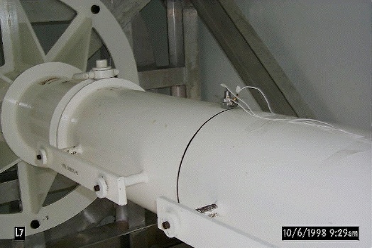
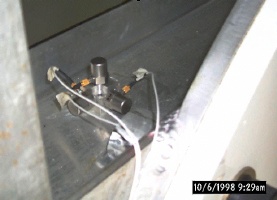
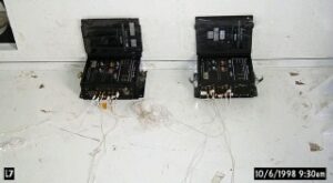
During pre-road test planning, Code 230 evaluated available IST instrumentation systems and concepts and optimized the test configuration and Recording Control Parameters (RCPs) for measuring and recording shock and vibration data. The Instrumentation team utilized two IST MSR1 Shock & Vibration Systems to collect and record data during the Road Test. Each MSR system consists of a recording box with six data channels and corresponding external accelerometers to acquire the data. Each external accelerometer measures one tri-axial channel of acceleration data (X, Y, and Z), or two tri-axial channels per box. The tri-axial accelerometers were mounted at a location on the mass simulator representing the spacecraft’s CG, two on the L-Frame fixture, and on an unisolated section of the trailer bed. Configuring an accelerometer in an unisolated section would allow the Instrumentation Team to analyze the LIS’s functionality. The LANDSAT mass simulator and L-Frame fixture are shown in figure 1, below. The IST accelerometer at the CG is observable above the CG line on the mass simulator. The three pictures in figure 2 are the remaining IST accelerometers and their mounting locations in the container.
Lessons Learned
Code 230 conducted the data analyses and was able to determine that the new container-isolation system would provide benign load and frequency transport environments during movement of the actual spacecraft. Additionally, Code 230 worked closely with IST engineers regarding "Lessons Learned" during the road test, which would be applied to the final move of the LANDSAT Spacecraft from LMMS in Valley Forge, Pa. to the processing facility at VAFB. A significant, technical "Lesson Learned" from the LANDSAT Test was that the shock and vibration data acquisition equipment Code 230 used for the LANDSAT Road Test did meet project data acquisition requirements. IST worked closely with Code 230 to evaluate the requirements and assisted Code 230 in the upgrade and purchase of advanced IST systems which would meet LANDSAT’s data acquisition needs. Based upon their research and recommendations, LANDSAT purchased an upgraded IST EDR-3D-10 recording box for use in the actual spacecraft transport. The EDR-3D-10 has one each internal and external tri-axial accelerometers, increasing data acquisition reliability. The EDR-3D-10 also has a "sliding window" capability, allowing data to be captured during discreet, pre-selected time intervals during transport.
Conclusion
The IST EDR-3D-10 recording system was used to monitor the spacecraft during actual transport to the launch site processing facility and again during transport from the processing facility to the launch pad. In both cases, analysis was able to verify a benign transport environment had been provided to the spacecraft.
NASA GSFC Code 230 is currently planning to utilize IST equipment on six identified road tests and transports during site in the upcoming year.
